
PART NUMBER |
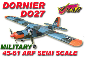
VMA-D260D Military & VMA-D260Z Civilian (Pirelli) |
| Please note: graphics and photos shown depict the Military Version unless specifically stated otherwise. Graphics details and color may vary slightly during production. | |
HISTORICAL INFO |
|
- First Introduced |
2002 10 15 |
- Availability Status |
Shipping as of 2003 01 25 |
- Supercedes |
Brand New Release |
- Superceded by |
Brand New Release |
| - Change Log Highlights | Click Here |
RECOMMENDED FOR |
Intermediate. Those who want an ARF that looks very much like the real thing! |
| HOURS TO FINISH | Eight |
. |
|
| INDEX to DETAILED INFORMATION & PICTURES. |
|
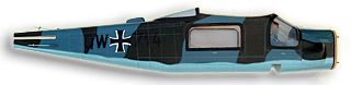
| PICTURES OF FUSELAGE | |
| All wood construction! No foam! Factory covered with POLYCOTE ECS. The graphics are inside the POLYCOTE ECS Enhanced Covering System! Note the scalloped camouflage edges and detailing all factory done without overlays and no decals! |
 |
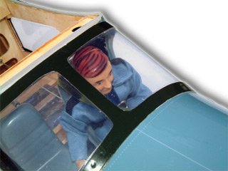
| More Pictures of Fuselage | |
| Cloth suited pilot and cockpit detailing! Note the formed seats, head and hands! Real fabric flight suit! |
|
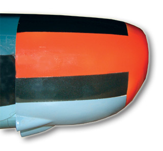
| Pre-finished fibreglass cowl! No painting required! Epoxy painted graphics that match the full size version! Complete with formed exhaust outlets! |
|
| PICTURES OF ENGINE MOUNT | |
| Picture of engine mount from right front |
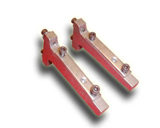 |
| More Pictures of Engine Mount | |
| PICTURES OF POWER MODULE | |
| Picture of Power Module System. Removeable forward firewall shown in place. Note thrust line indicated on forward face. |
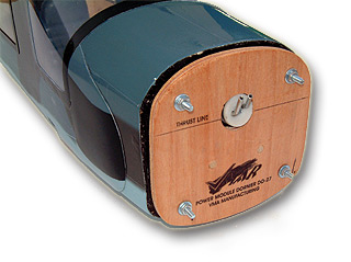 |
| More Pictures of Power Module | |
| PICTURES OF LANDING GEAR | |
| Picture of main landing gear. Wire gear comes complete with pre-installed spats (blue) and struts (gray) with wheel collars and set screws. |
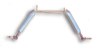 |
| More Pictures of Landing Gear | |
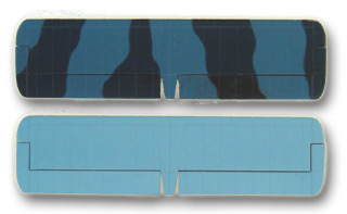
| PICTURES OF WING | |
| Top of rIght wing and bottom of left wing. Note servo cover plates on bottom of wing. Inboard servo is for flaps (usage is optional) and outboard servo is for flaps. Cavity visible near root provides for servo wiring exit into fuselage. Wiring tubes preinstalled in wing. |
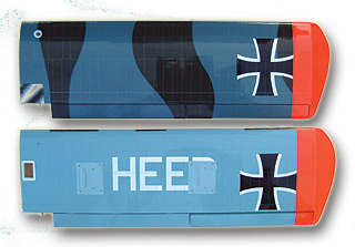 |
| More Pictures of Wing | |
| Picture of horizontal stabilizer. Top and bottom views are very different. |
 |
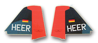
| PICTURES OF VERT STAB/RUDDER | |
Picture of vertical stabilizer and rudder. Left and right views are similar.
|
 |
| More Pictures of Vert Stab/Rudder | |
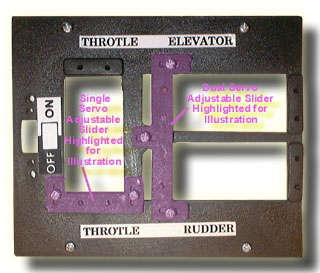
| PICTURES OF SERVO TRAY | |
| Picture of servo tray with universally adjustable sliders highlighted in purple shading. Adjust to fit length of Futaba, Airtronics, JR or Hi-Tech standard servo. Tighten screws to lock slider into position. |
 |
| More Pictures of Servo Tray | |
| PICTURES OF DISPLAY BOX | |
| Picture of front of display box. |
 |
| More Pictures of Display Box | |
![]()
![]()
| ©Richmond RC Supply Ltd. All Rights Reserved. Unauthorized commercial use strictly prohibited. |
| Prices, Specifications, Features and Availability subject to change without notice |
| Production Colors and Graphic Schemas may differ from that shown. |
| Artwork, text and information for the use of consumers and Richmond RC customers only |
| For information contact webmaster@richmondrc.com |
2003-09-20 21:49:50