
PART NUMBER |
VMA-P240A Australian RAAF Roulette Demonstration Aerobatics Team |
||||||||||||||||||||||||||||||||||||
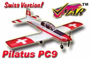
| VMA-P240S Swiss Version | |||||||||||||||||||||||||||||||||||||
| Please note: graphics and photos shown depict the Australian Version unless specifically denoted "Swiss Version". | |||||||||||||||||||||||||||||||||||||
HISTORICAL INFO |
|||||||||||||||||||||||||||||||||||||
- First Introduced |
2001 01 01 |
||||||||||||||||||||||||||||||||||||
- Availability Status |
Booking for April 2001 |
||||||||||||||||||||||||||||||||||||
- Supercedes |
Brand New Release |
||||||||||||||||||||||||||||||||||||
- Superceded by |
Brand New Release | ||||||||||||||||||||||||||||||||||||
| - Change Log Highlights | Click Here | ||||||||||||||||||||||||||||||||||||
RECOMMENDED FOR |
Intermediate. Great for Sport Scale. Officially classed as Semi-Scale with unbelievable resemblance and detailing to match the real thing. |
||||||||||||||||||||||||||||||||||||
HOURS TO FINISH |
Eight |
||||||||||||||||||||||||||||||||||||
| INDEX to DETAILED INFORMATION | |||||||||||||||||||||||||||||||||||||
- Location on Fuselage |
Below Fuselage |
||||||||||||||||||||||||||||||||||||
- Span |
57-3/4 in. (1467 mm) |
||||||||||||||||||||||||||||||||||||
- Area* |
540 sq in. (3484 sq cm) |
||||||||||||||||||||||||||||||||||||
- Airfoil |
Symmetrical |
||||||||||||||||||||||||||||||||||||
- Taper |
Yes. Leading and Trailing Edge Taper |
||||||||||||||||||||||||||||||||||||
- Chord Size |
Root = 10-3/8 (264 mm). Tip = 7-7/8 in. (200 mm) |
||||||||||||||||||||||||||||||||||||
- Thickness |
1-3/4in. (44 mm) |
||||||||||||||||||||||||||||||||||||
- Construction |
Wood - Built Up |
||||||||||||||||||||||||||||||||||||
- Aileron Type |
Strip with pre-installed torque rods |
||||||||||||||||||||||||||||||||||||
- Ailerons Pre-Hinged? |
Yes. 4 Hinges per Aileron |
||||||||||||||||||||||||||||||||||||
| - Hinges Factory Pinned? | Yes. 4 pins per inboard & outboard hinge. 2 pins per centre hinge.. | ||||||||||||||||||||||||||||||||||||
- Hinge Type |
Real Hinge with Metal Pin |
||||||||||||||||||||||||||||||||||||
| - Flap Type | na | ||||||||||||||||||||||||||||||||||||
| - Flaps Pre-Hinged? | na | ||||||||||||||||||||||||||||||||||||
| - Flaps Factory Pinned? | na | ||||||||||||||||||||||||||||||||||||
- How Joined? |
Wood Dihedral Spar Joiner & 2 Wood Alignment Pins |
||||||||||||||||||||||||||||||||||||
- How Mount to Fuse? |
2 Fixed Dowels in leading edge of wing and 2 Nylon Bolts near trailing edge. |
||||||||||||||||||||||||||||||||||||
- Servo for Wing? |
Yes only 1 needed. |
||||||||||||||||||||||||||||||||||||
- Servo Location |
Top centre of Wing. |
||||||||||||||||||||||||||||||||||||
- Second Wing Servo |
Not required and not specifically provided for. A second servo can be fitted with minor modifications to wing skin |
||||||||||||||||||||||||||||||||||||
- Color Top |
Red and white with blue trim, black lettering & gray rivets & panel lines. | ||||||||||||||||||||||||||||||||||||
- Color Bottom |
Red and white with blue trim & gray rivets & panel lines. | ||||||||||||||||||||||||||||||||||||
- Color Pattern Top vs Bottom |
Very Similar |
||||||||||||||||||||||||||||||||||||
| - Picture of Wing Top and Bottom.
|
 |
||||||||||||||||||||||||||||||||||||
| Blowup of wing graphic detailing with panel lines and rivets. |  |
||||||||||||||||||||||||||||||||||||
- Length* |
47-50 in. (1194 - 1270 mm) depending on engine and installation. |
||||||||||||||||||||||||||||||||||||
- Construction |
Wood - Built Up |
||||||||||||||||||||||||||||||||||||
- Pushrods |
Preinstalled |
||||||||||||||||||||||||||||||||||||
- Pushrod Material |
Steel Rods w/thread on both ends. Running in plastic guide tubes. Plain rod with EZ Connector & Z-Bend for Nose Gear Steering. [Variable Length two piece rod for throttle w/thread on both ends.] |
||||||||||||||||||||||||||||||||||||
- Servo Tray |
Pre-installed. Universal Adjustable for F/JR/Air/HiT |
||||||||||||||||||||||||||||||||||||
- Color |
Red and white with blue & yellow trim, black lettering & gray rivets & panel lines. | ||||||||||||||||||||||||||||||||||||
- Servos Needed? |
1 Throttle, 1 Elevator, 1 Rudder |
||||||||||||||||||||||||||||||||||||
- Servo Locations |
Tray Centre Inside Fuselage. |
||||||||||||||||||||||||||||||||||||
|
- Picture of Fuselage Cockpit as seen from left rear quarter. Note Detailing on of pilots and instructment panel.
|
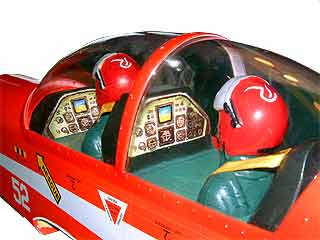 |
||||||||||||||||||||||||||||||||||||
| - Picture of Fuselage as seen from right side. |  |
||||||||||||||||||||||||||||||||||||
| - Horiz Stab Span | 21-7/8 in. (556 mm) | ||||||||||||||||||||||||||||||||||||
- Horiz Stab Area* |
80 sq in. (516 sq cm) | ||||||||||||||||||||||||||||||||||||
| - Horiz Stab Construction | One Piece - Wood - Built Up | ||||||||||||||||||||||||||||||||||||
- Elevator Area |
47 sq in. (303 sq cm) each. Two independent elevators. | ||||||||||||||||||||||||||||||||||||
- Elevator Construction |
One Piece - Wood - Built Up |
||||||||||||||||||||||||||||||||||||
- Pre-Hinged |
Yes. 6 Hinges. |
||||||||||||||||||||||||||||||||||||
| - Hinges Factory Pinned? | Yes. All elevator hinges are pinned. 4 pins per hinge inboard and outboard. 2 pins per hinge centre 4 hinges. | ||||||||||||||||||||||||||||||||||||
- Hinge Type |
Real Hinge with Metal Pin. |
||||||||||||||||||||||||||||||||||||
- Airfoil |
Slab. |
||||||||||||||||||||||||||||||||||||
- How Mount to Fuse? |
Install into machined slot in fuselage and glue with 30 Minute Epoxy. |
||||||||||||||||||||||||||||||||||||
- Support Struts? |
No. Not Required |
||||||||||||||||||||||||||||||||||||
- Color Top |
Red and white with blue trim & gray rivets & panel lines. | ||||||||||||||||||||||||||||||||||||
- Color Bottom |
Red and white with blue trim & gray rivets & panel lines. | ||||||||||||||||||||||||||||||||||||
- Color Pattern Top vs Bottom |
Same |
||||||||||||||||||||||||||||||||||||
| - Picture of Horizontal Stabilizer and Elevator. Top and Bottom views are identical. |  |
||||||||||||||||||||||||||||||||||||
- Vertical Stab Area* |
35 sq in. (226 sq cm) | ||||||||||||||||||||||||||||||||||||
- Rudder Area |
23 sq in. (148 sq cm) | ||||||||||||||||||||||||||||||||||||
- Construction |
Wood - Built Up |
||||||||||||||||||||||||||||||||||||
- Pre-Hinged |
Yes. 3 Hinges. |
||||||||||||||||||||||||||||||||||||
| - Hinges Factory Pinned? | Yes. 4 pins per hinge top and bottom hinge. | ||||||||||||||||||||||||||||||||||||
- Hinge Type |
Real Hinge with Metal Pin |
||||||||||||||||||||||||||||||||||||
- Airfoil |
Slab |
||||||||||||||||||||||||||||||||||||
- How Mount to Fuse? |
Install into machined slot in fuselage and glue with 30 Minute Epoxy. |
||||||||||||||||||||||||||||||||||||
- Color |
Red and white with blue trim, black lettering & gray rivets & panel lines. | ||||||||||||||||||||||||||||||||||||
| - Color Pattern Left vs Right | Same | ||||||||||||||||||||||||||||||||||||
| - Picture of Vertical Stabilizer and Rudder. Left and Right views are identical |  |
||||||||||||||||||||||||||||||||||||
- "Sure Seal" |
Thermal Shrink Film |
||||||||||||||||||||||||||||||||||||
- Self Adhesive |
Low Temperature |
||||||||||||||||||||||||||||||||||||
- Patchable |
Yes. Use patch sheet provided or aftermarket use Ultracote Plus or Ultracote Regular. |
||||||||||||||||||||||||||||||||||||
- Patch Sheet Provided? |
Yes Red. Use Factory Patch Sheets if possible. Aftermarket covering will not match colors exactly. |
||||||||||||||||||||||||||||||||||||
| - Ultracote
System Approx
Color Match
Note: We recommend Ultracote Plus and a Heat GUN for patching using after market covering. Note: Color Names with * are poor matches to factory colors. |
|
||||||||||||||||||||||||||||||||||||
Trike |
|||||||||||||||||||||||||||||||||||||
- Main Gear |
5/32 in. (4 mm) steel wire pre-bent and chromed |
||||||||||||||||||||||||||||||||||||
| - Stance - Between Wheels | 13 in. (330 mm) between inboard side of wheels. | ||||||||||||||||||||||||||||||||||||
- Main Wheels |
Two of 2-7/16 in. (62 mm) Ultralight Treaded. |
||||||||||||||||||||||||||||||||||||
| - Main Wheel Pants | na | ||||||||||||||||||||||||||||||||||||
| - Wheels Pants made of? | na | ||||||||||||||||||||||||||||||||||||
| - Main Gear Struts? | Yes. Scale like molded struts pre-installed over main gear wires. | ||||||||||||||||||||||||||||||||||||
| - Retract Ready? | na | ||||||||||||||||||||||||||||||||||||
| - Retracts that fit... | na | ||||||||||||||||||||||||||||||||||||
- Nose Gear |
5/32 in. (4 mm) Wire |
||||||||||||||||||||||||||||||||||||
- Nose Wheel |
One of 2-7/16 in. (62 mm) Ultralight Treaded |
||||||||||||||||||||||||||||||||||||
| - Nose Wheel Pants | na | ||||||||||||||||||||||||||||||||||||
| - Nose Wheel Pant made of? | na | ||||||||||||||||||||||||||||||||||||
| - Nose Gear Strut? | Yes. Scale like molded strut pre-installed over nose gear wire. | ||||||||||||||||||||||||||||||||||||
- Tail Wheel Assembly |
na. Trike Gear |
||||||||||||||||||||||||||||||||||||
- Tail Wheel |
na. Trike Gear |
||||||||||||||||||||||||||||||||||||
| - Tail Wheel Steering Mechanism | na. Trike Gear |
||||||||||||||||||||||||||||||||||||
| - Picture of Main Gear, Nose Gear, Clamps, Wheels, Wheel Collars, Gear Doors and pre-mounted Struts as provided in hardware pack. |  |
||||||||||||||||||||||||||||||||||||
| - Picture of strut assembly as pre-mounted on all three landing gear legs.. | 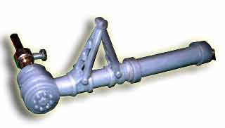 |
||||||||||||||||||||||||||||||||||||
| - included | Yes with scale like exhaust stacks. | ||||||||||||||||||||||||||||||||||||
| - material | Fibreglass | ||||||||||||||||||||||||||||||||||||
| - color | True Red with black stacks. | ||||||||||||||||||||||||||||||||||||
| - trim supplied | Painted with Epoxy | ||||||||||||||||||||||||||||||||||||
| - trim applied by? | Factory | ||||||||||||||||||||||||||||||||||||
| - Picture of Fibreglass Cowl from front and top. Note scale detailing of exhaust stack. Completely painted and ready to mount out of the box. |  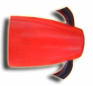 |
||||||||||||||||||||||||||||||||||||
Not included. See Options |
|||||||||||||||||||||||||||||||||||||
- 2 cycle |
.46-.60 cu in. (6.5-10cc). GMS-47PRO or Enya 50CX Recommended. For High Performance use GMS-61PRO or Enya 60XF4ALC |
||||||||||||||||||||||||||||||||||||
- 4 cycle |
.53-.70cu in. (8-12 cc) | ||||||||||||||||||||||||||||||||||||
T-bar Beams. Aluminum Clamp Type all pretapped |
|||||||||||||||||||||||||||||||||||||
- Firewall Predrilled for Mount? |
No. To allow after market orientation of engine |
||||||||||||||||||||||||||||||||||||
- Predrilled orientation choices |
Modellers choice |
||||||||||||||||||||||||||||||||||||
- Orientation Recommended |
Modellers choice |
||||||||||||||||||||||||||||||||||||
- Mount Installed? |
No. To allow after market orientation of engine |
||||||||||||||||||||||||||||||||||||
| - Engine Lug Length - Max | 1-5/8 in. (41 mm) | ||||||||||||||||||||||||||||||||||||
| - Engine Width - Max | Upright
Mounting - 1-9/16 in. (39mm). Can be increased to approximatley 2-3/4 in.
(70mm) by setting gap between aft fixed firewall and forward removable
firewall to be 1/4 in. (6 mm) using hardware provided.
Inverted - same as upright. Will require use of muffler extension for most engines to allow muffler to clear side of fuselage. 45 or 135 or 225 degrees... approximately 2 in. (51mm) by setting gap between aft fixed firewall and forward removable firewall to be 1/4 in. (6 mm) using hardware provided. Note that T-beam engine mounts are normally utilized with clamp side towards head of engine. In some cases installation can be easier with one or both of the T-beams positioned so that the clamp side faces away from the engine head. |
||||||||||||||||||||||||||||||||||||
| - Beam Length | 2-7/8 in. (73 mm) flat useable. 3-1/2 in. (89mm) from firewall to tips. | ||||||||||||||||||||||||||||||||||||
| - Picture of Engine Mount. Front View. Clamps can accomodate wide range of engine mounting lug sizes. | 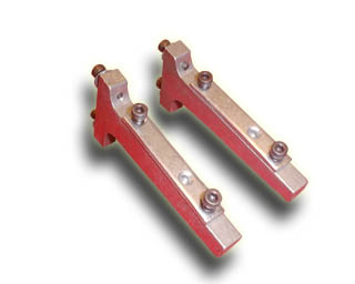 |
||||||||||||||||||||||||||||||||||||
- Power Module System |
Yes. Fixed firewall aft. Removable firewall forward secured to aft firewall with mounting bolt system. Engine mounts, tank & engine mounted to removeable firewall. |
||||||||||||||||||||||||||||||||||||
| - Picture of Power Module partially removed from fuselage showing forward removeable firewall with tank (right) and fuselage with aft fixed firewall and retaining studs (left). |  |
||||||||||||||||||||||||||||||||||||
| - Picture of Engine Mounts and Engine Installed on forward removeable firewall prior to inserting power module into fuselage. Note Engine is at approx 195 degree rotation from upright. | 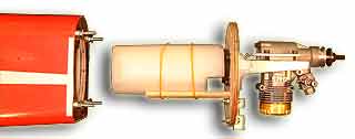 |
||||||||||||||||||||||||||||||||||||
| More Pictures of Power Module | |||||||||||||||||||||||||||||||||||||
Not included. See options |
|||||||||||||||||||||||||||||||||||||
- 4 channels |
Need 4 servos. |
||||||||||||||||||||||||||||||||||||
| SERVO TRAY | Preinstalled. Universal adjustable for F/JR/Air/HiT. | ||||||||||||||||||||||||||||||||||||
| - Picture of Servo Tray with universally adjustable sliders highlighted in purple shading. Adjust to fit length of Futaba, Airtronics, JR or Hi-Tech standard servo. Tighten screws to lock slider into position. | 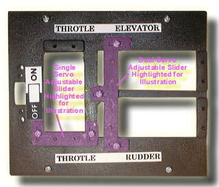 |
||||||||||||||||||||||||||||||||||||
- Type |
Plastic |
||||||||||||||||||||||||||||||||||||
- Size |
10.5 oz (300 cc) |
||||||||||||||||||||||||||||||||||||
- Clunk |
Yes |
||||||||||||||||||||||||||||||||||||
- Silicone Tubing |
No |
||||||||||||||||||||||||||||||||||||
- Metal Tubing |
2 - Prebent & fitted in stopper |
||||||||||||||||||||||||||||||||||||
| HARDWARE SET | |||||||||||||||||||||||||||||||||||||
- Empty* - Assembled |
4-1/4 - 4-3/4 lbs (1932 - 2158 g) | ||||||||||||||||||||||||||||||||||||
- Flying Dry* - 2 cycle |
5-1/2 - 6 lbs (2500 - 2730 g) | ||||||||||||||||||||||||||||||||||||
- Flying Dry* - 4 cycle |
6 - 6-1/2 lbs (2730 - 2950 g) | ||||||||||||||||||||||||||||||||||||
- Empty* - Assembled |
19.2 oz/sq ft @ 4-1/2 lbs | ||||||||||||||||||||||||||||||||||||
- Flying Dry* - 2 cycle |
24.5 oz/sq ft @ 5-3/4 lbs | ||||||||||||||||||||||||||||||||||||
- Flying Dry* - 4 cycle |
26.7 oz/sq ft @ 6-1/4 lbs | ||||||||||||||||||||||||||||||||||||
- CG Location |
3 to 3-1/2 in. (78-86 mm) back from the leading edge of the wing with the tank installed but empty. Ideally 3-1/4 (82 mm) back from leading edge of the wing with tank empty. CG is measured with the engine, tank, radio gear and all components installed but WITH NO FUEL IN THE TANK. | ||||||||||||||||||||||||||||||||||||
| - Aileron Throw. (Use Low Rate for first flights and all training and/or if your radio does not support dual rates) |
|
||||||||||||||||||||||||||||||||||||
| - Rudder Throw at Widest section of Rudder. (Use Low Rate for first flights and all training and/or if your radio does not support dual rates) |
|
||||||||||||||||||||||||||||||||||||
| - Elevator Throw (Use Low Rate for first flights and all training and/or if your radio does not support dual rates) |
|
||||||||||||||||||||||||||||||||||||
| - Flaps Throw | na | ||||||||||||||||||||||||||||||||||||
| - Tailwheel Throw | na. Trike Gear | ||||||||||||||||||||||||||||||||||||
- Engine Horizontal Thrust Line |
Factory line across front face of forward removable firewall. Approximately 1-3/4 in. (44 mm) down from top of fuselage at firewall. |
||||||||||||||||||||||||||||||||||||
| - Engine Vertical Thrust Line | Vertically up and down through centre of forward removeable firewall and lieing perpendicular to the horizontal thrust line. | ||||||||||||||||||||||||||||||||||||
- Engine Thrust Angle. |
None. 1-3 degrees of right thrust may assist with take offs but is not required. The power module system allows modellers to easily set any particular horizontal and/or vertical thrust at any time before or after assembly. |
||||||||||||||||||||||||||||||||||||
- Cardboard |
Brown |
||||||||||||||||||||||||||||||||||||
- Size Length x Width x Depth |
43-3/16 x 13-11/16 x 8-9/16 in. (1096 x 348 x 217 mm) |
||||||||||||||||||||||||||||||||||||
- Length plus Girth |
87-5/8 in. (2226 mm) | ||||||||||||||||||||||||||||||||||||
- Volume |
2.93 cu ft (.0828 cu m) | ||||||||||||||||||||||||||||||||||||
- Weight with kit |
11 lbs 7 oz (5199 g) | ||||||||||||||||||||||||||||||||||||
| - Other Info | na | ||||||||||||||||||||||||||||||||||||
| SHIPPING INFO | |||||||||||||||||||||||||||||||||||||
| - Shipping Method in Canada. | Canpar most locations (enroute time 1-3 business days west, 5-10 business days east). Canada Post to remote locations in the south and to YT, NWT, Nunavut in the north. | ||||||||||||||||||||||||||||||||||||
| - Shipping Method to USA lower 48 states | FedEx Ground (enroute time 5-10 business days west, 10-14 business days east) | ||||||||||||||||||||||||||||||||||||
| - Shipping method to Hawaii, USA, APO or USA possessions. | United States Postal Service Priority Mail (enroute time approx 7 business days) | ||||||||||||||||||||||||||||||||||||
| - Shippable outside Canada or USA by Air or Surface Mail? | - No. Length plus Girth exceeds limit of 78.8 in (2 m) and/or Length exceeds limit of 39.4 in. (1 m) | ||||||||||||||||||||||||||||||||||||
| - Shippable outside Canada or USA by Air or Surface Mail if separated into multiple boxes? | - No. Fuselage length exceeds length limit of 39.4 in. (1 m) | ||||||||||||||||||||||||||||||||||||
| - Shippable outside Canada or USA by Fedex? | Yes. Refer to www.fedex.com for quote to your location. Size, weight and location will be required. See box sizes and weights above. | ||||||||||||||||||||||||||||||||||||
| - Cardboard | White | ||||||||||||||||||||||||||||||||||||
| - Protected by | Plastic Bag & Shipping Box | ||||||||||||||||||||||||||||||||||||
| - Size Length x Width x Depth | 42-3/16 x 13-3/16 x 8-1/16 in. (1072 x 335 x 205 mm) | ||||||||||||||||||||||||||||||||||||
| - Length plus girth | 84-3/4 in. (2152 mm) | ||||||||||||||||||||||||||||||||||||
| - Volume | 2.60 cu ft (.0733 cu m) | ||||||||||||||||||||||||||||||||||||
| - Weight with kit & protective plastic bag. | 9 lbs 7 oz (4290 g) | ||||||||||||||||||||||||||||||||||||
| - Label covers all of Display Box | 98% Coverage. | ||||||||||||||||||||||||||||||||||||
| - Label front colors | Colors = Four color process.Mainly white, red and blue. | ||||||||||||||||||||||||||||||||||||
| - Label front size | 42-3/16 x 13-3/16 in. (1072 x 335 mm) | ||||||||||||||||||||||||||||||||||||
| - Label front picture |  |
||||||||||||||||||||||||||||||||||||
| - Label side panel colors | Colors = Four color process.Mainly white, red and blue. | ||||||||||||||||||||||||||||||||||||
| - Label side panel size | 42-3/16 x 8-1/16 in. (1072 x 205 mm) | ||||||||||||||||||||||||||||||||||||
| - Label left and right sides pictures | 
|
||||||||||||||||||||||||||||||||||||
| - Label end panel colors | Colors = Four color process.Mainly white, red and blue. | ||||||||||||||||||||||||||||||||||||
| - Label end panel size | 13-3/16 x 8-1/16 in. (335 x 205 mm) | ||||||||||||||||||||||||||||||||||||
| - Label end panel picture |  |
||||||||||||||||||||||||||||||||||||
| - Accuracy of Dimensions | Dimensions provided here are within +/- 3% in production. | ||||||||||||||||||||||||||||||||||||
- na |
Not applicable this model |
||||||||||||||||||||||||||||||||||||
| - blank data or information | Not known at this time | ||||||||||||||||||||||||||||||||||||
| - [info?] | Estimated. Yet to be confirmed. | ||||||||||||||||||||||||||||||||||||
- Area* of Wing |
Includes wing saddle area, ailerons & flaps where fitted. |
||||||||||||||||||||||||||||||||||||
| - Area* of Horizontal Stab. | Does not include area of elevator(s). | ||||||||||||||||||||||||||||||||||||
| - Area* of Vertical Stabilizer | Does not include area of rudder. | ||||||||||||||||||||||||||||||||||||
- Length* of Fuse |
From Spinner back plate to Trailing Edge of Rudder |
||||||||||||||||||||||||||||||||||||
- Empty* Weight |
No radio, engine or fuel |
||||||||||||||||||||||||||||||||||||
- Flying Dry* Weight |
With radio, engine. No fuel |
||||||||||||||||||||||||||||||||||||
- Flying Dry* Loading |
With radio, engine. No fuel |
![]()
![]()
| �Richmond RC Supply Ltd. All Rights Reserved. Unauthorized commercial use strictly prohibited. |
| Prices, Specifications, Features and Availability subject to change without notice |
| Production Colors and Graphic Schemas may differ from that shown. |
| Artwork, text and information for the use of consumers and Richmond RC customers only |
| For information contact webmaster@richmondrc.com |
2004-06-13 15:35:10