Annotated Illustration of Typical VMAR Power Module System
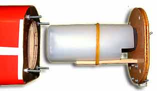
Picture of fuselage with aft fixed firewall and retaining studs. Power Module consisting of forward removable firewall and tank has been completely removed from fuselage
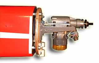
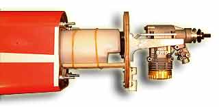
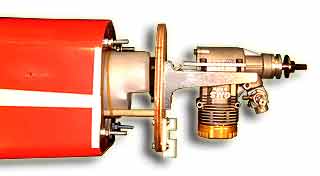
Picture of Engine Mounts and Engine installed on forward removable firewall prior to inserting power module into fuselage. In this example, the engine is at approx 195 degree rotation from upright.
Picture similar to above taken from right front quarter.
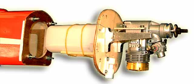
Picture of Power Module during insertion process. The forward removable firewall and tank assembly (right) are slid into the fuselage to mate with the fixed aft firewall (left).
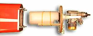
Picture showing almost fully inserted Power Module.
Picture showing completely inserted and installed Power Module after retaining nuts applied to studs.